
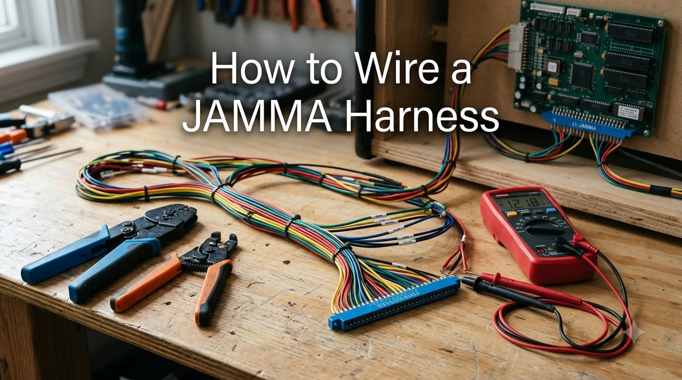
Wiring a JAMMA harness is the single most important skill for anyone restoring or building an arcade cabinet. The JAMMA standard lets you connect any compatible game board to your cabinet’s controls, power, video, and audio using one standardized wiring system. Once you understand the pinout and follow a logical sequence, the process becomes straightforward.
In this guide, I will walk you through how to wire a JAMMA harness from start to finish. I have spent years working on arcade restorations, and I will share the exact steps, tools, and common pitfalls I have encountered along the way. By the end, you will be able to install a harness, connect every component correctly, and power up your cabinet with confidence.
Whether you are building a multicade from scratch or swapping a PCB in a vintage cabinet, this guide covers everything you need. I will include the full JAMMA pinout reference, safety precautions that most guides skip, and troubleshooting tips drawn from real forum discussions.
Table of Contents
What Is JAMMA and Why It Matters?
JAMMA stands for Japan Amusement Machinery Manufacturers Association, the trade group that created this wiring standard in the late 1980s. Before JAMMA, every arcade manufacturer used proprietary wiring, which meant swapping a game board required completely rewiring the cabinet. JAMMA changed that by establishing a universal 56-pin connector that every manufacturer could adopt.
The JAMMA harness uses a .187 inch (3.96 mm) card-edge connector that plugs directly into the game PCB. This single connector carries all power, ground, video, audio, and control signals between the board and the cabinet. You wire the harness to your cabinet’s components once, then any JAMMA-compatible PCB plugs right in without further modification.
The standard supports two players, each with joysticks and up to three buttons natively. Many modern harnesses extend this to six buttons per player using kick harness extensions. Power runs at +5VDC for logic, +12VDC for audio amplifiers, and -5VDC for older boards that need negative voltage for their sound circuits.
Tools and Materials You Need
Having the right tools before you start will save you hours of frustration. Here is what I recommend based on dozens of cabinet builds and restorations.
Essential tools:
Wire crimper for .187 inch (3.96 mm) spade connectors
Wire stripper capable of handling 18 AWG to 22 AWG wire
Digital multimeter for voltage testing and continuity checks
Needle-nose pliers for connector placement
Heat shrink tubing and a heat gun
Soldering iron (optional, for permanent joins)
Zip ties for wire management
Materials:
Standard 56-pin JAMMA harness (color-coded recommended)
Quick-disconnect spade connectors (.187 inch for most microswitches)
18 AWG wire for power lines (handles current safely)
20-22 AWG wire for signal and control lines
5 amp fast-blow fuse for the +5V line
Heat shrink or electrical tape for insulation
I cannot stress enough how important wire gauge is. Using wire that is too thin for power lines can cause voltage drops, which leads to glitchy graphics or random resets. Stick with 18 AWG for anything carrying +5V or +12V, and never go below 20 AWG for ground lines.
Understanding the JAMMA Pinout
The JAMMA pinout defines exactly what each of the 56 pins on the card-edge connector does. Understanding this layout is the foundation of every successful wiring job. The connector has two sides: the parts side (component side, labeled S) and the solder side (labeled P). Each side has 28 pins, numbered from the key slot outward.
The pins fall into five main categories. Here is how they break down so you know what connects where.
Power pins: The parts side includes multiple +5V, +12V, and GND pins that supply electricity to the PCB. The solder side mirrors these power connections. You must connect every power and ground pin to the corresponding terminal on your arcade power supply.
Ground pins: Ground connections appear on both sides of the connector and are critical for completing circuits. Missing a ground connection is the most common cause of video problems and unresponsive controls.
Control signal pins: Each joystick direction and button has a dedicated signal pin, plus a shared ground. Player 1 controls occupy pins on the lower section of the connector, while Player 2 controls are on the upper section.
Video output pins: The PCB outputs Red, Green, Blue, Composite Sync, and Video Ground through specific pins. These connect to your monitor’s input, whether it is a CRT with CGA input or an LCD using a converter.
Audio output pins: Speaker positive and negative pins carry amplified sound directly to your cabinet speaker. Some boards output line-level audio instead, which requires an external amplifier.
Here is a quick reference for the most commonly used JAMMA pins. I recommend printing this out and keeping it at your workbench.
Key JAMMA Pinout Reference:
Parts Side: Pins A1-A4 = GND | A5 = -5V | A6-A7 = +5V | A8-A9 = +12V | A10 = Key | A11-A12 = +5V
Solder Side: Pins B1-B3 = GND | B4 = -5V | B5-B6 = +5V | B7 = +12V | B8 = Key | B9-B10 = +5V
Parts Side C-D pins: Player 1 joystick (up/down/left/right), buttons 1-3, Player 2 controls, buttons 4-6
Parts Side E-F pins: Coin counter, service, test, coin switch inputs for both players
Solder Side pins 11-18: Video R, G, B, Sync, Video Ground
Solder Side pins 20-28: Speaker output (L and R), audio ground
Notice that power and ground pins are duplicated across multiple positions. This is by design. The redundancy distributes current load and prevents voltage drops. Never skip connecting any of these pins.
How to Wire a JAMMA Harness: Step by Step
Now I will walk through the complete wiring process. Follow these steps in order, and test after each major connection before moving on.
Step 1: Plan Your Layout and Prepare the Harness
Before cutting or crimping anything, lay the harness out inside your cabinet. Route the JAMMA connector to where your PCB will sit, and distribute the wire bundles toward their respective destinations: power supply, control panel, coin door, monitor, and speaker. Trim wires to length with a few inches of slack. It is much easier to plan now than to extend wires later.
Identify the wire colors on your harness. Most quality harnesses follow a color convention, but never assume. Always cross-reference with a pinout diagram. I keep a printed pinout taped to the inside of every cabinet I work on.
Step 2: Connect the Power Wires
Power wiring is the most critical step, and errors here can damage your PCB. Start by identifying all +5V, +12V, -5V, and GND wires from your harness. These typically use heavier gauge wire and cluster near the key slot on the connector.
Connect the +5V wires to the +5V terminal on your arcade power supply. Do the same for +12V and -5V to their respective terminals. Then connect every ground wire to the power supply’s ground terminal. Use ring terminals or spade connectors that match your power supply’s screw terminals, and crimp them securely.
Once connected, power up the supply without the PCB installed. Use your multimeter to verify +5V reads between 4.9V and 5.1V at the JAMMA connector’s power pins. Check +12V reads close to 12V. If any voltage is off, adjust your power supply before proceeding.
Step 3: Wire the Control Panel
Control panel wiring connects your joysticks and buttons to the JAMMA harness signal pins. Each microswitch on a joystick or button has two terminals: the signal contact (NO, normally open) and a ground terminal (COM).
For Player 1, find the harness wires for up, down, left, right, and buttons 1 through 3 (or 1 through 6 on extended harnesses). Crimp a .187 inch quick-disconnect onto each signal wire and attach it to the NO terminal of the corresponding microswitch. Then Daisy-chain the ground wires and connect them to the COM terminal on each switch.
The Daisy-chain ground method is standard practice. You run one ground wire from the harness through the COM terminal of each switch in sequence. This creates a shared ground loop that keeps wiring clean and ensures every switch has a solid ground reference.
Repeat the same process for Player 2 controls. Remember that Player 2 has its own set of signal pins on the JAMMA connector, so double-check that you are using the correct wires from the harness.
Step 4: Wire the Coin Door and Service Switch
The coin door wiring connects the coin mechanisms and service buttons to the JAMMA harness. Each coin slot has a microswitch that registers when a coin passes through. Wire the coin switch signal wires from the harness to the NO terminals on your coin mech switches, and add them to the ground daisy chain.
Most cabinets also have a test button and service button, usually located inside the coin door area. The test button enters the game’s diagnostic menu, while the service button advances through menu options and adds credits without coins. Wire these to their designated JAMMA pins.
If your harness includes coin counter outputs, these connect to the 12V coil on the coin counter meter. These are low priority for function but completing the wiring keeps everything tidy.
Step 5: Connect the Video Output
Video wiring carries the RGB signal from the PCB to your monitor. Find the Red, Green, Blue, Composite Sync, and Video Ground wires from the harness. Connect each color signal to the corresponding input on your monitor’s chassis or video input board.
Video Ground is essential. I see builders skip it constantly because they assume the main ground handles everything. Video Ground is a separate pin specifically for the monitor’s reference level. Without it, you get rolling pictures, wavy lines, or no image at all. Always connect it.
If your cabinet uses a CRT monitor with CGA input, the RGB and sync wires connect directly to the chassis header. For LCD monitors, you will need a CGA-to-VGA converter. Connect the JAMMA video wires to the converter’s input, then run a VGA cable from the converter to the monitor.
Step 6: Connect the Audio
JAMMA audio is amplified at the PCB level and sent through the speaker output pins. Find the Speaker+ and Speaker- wires on the harness and connect them to your cabinet speaker. Observe polarity, as reversing it can cause phase issues or reduced volume.
Some modern boards output line-level audio instead of amplified audio. If your speaker is passive and the board outputs line-level, you need an external amplifier between the JAMMA speaker pins and the speaker. Check your PCB’s documentation to confirm which type it uses.
For cabinets using Pandora’s Box or similar multicade boards, the audio is typically amplified and connects directly. If you hear distortion at high volume, add a 470 ohm resistor in series with the speaker line. Forum users report this fix commonly improves audio clarity.
Step 7: Install the PCB and Test
With all connections made, carefully plug the JAMMA harness connector onto the PCB’s card-edge. The connector has a key slot that prevents insertion in the wrong direction, but always verify orientation before applying force.
Power on the cabinet and immediately watch for smoke, burning smells, or unusual heat. If anything seems wrong, cut power instantly. Check the voltages at the PCB using your multimeter while the board is running. The +5V should hold steady under load.
If everything checks out, you should see the game boot on screen, hear sound from the speaker, and have working controls. Test every button and joystick direction. If something does not work, refer to the troubleshooting section below before making changes.
Safety Precautions for Arcade Wiring
Arcade cabinets carry dangerous voltages, and safety must come first. Your arcade power supply converts wall AC (110V or 220V) down to the low DC voltages the PCB uses. Never open or modify the power supply enclosure. The AC input side carries lethal voltage.
Always unplug the cabinet from the wall before making any wiring changes. This is non-negotiable. Even when the power switch is off, some cabinets keep live AC on the input side of the switch. Pulling the plug is the only way to be certain.
If your cabinet has a CRT monitor, be aware that the tube retains a high-voltage charge even after being unplugged. The anode cap on a CRT can hold up to 25,000 volts for days. If you need to work near the monitor chassis, discharge the tube first using a properly insulated discharge tool. Never touch the anode cap or flyback transformer with bare hands.
Use properly rated fuses on all power lines. The standard arcade power supply has built-in fusing, but adding a 5 amp fast-blow fuse on the +5V line provides extra protection for your PCB. A short circuit without a fuse can destroy traces on the board instantly.
Keep your work area dry and well-lit. Water and electronics do not mix, and poor lighting leads to wiring mistakes. Wear safety glasses when crimping or cutting wire, as small fragments can fly off.
Common Mistakes and How to Avoid Them
I have seen the same mistakes repeated across countless forum posts and cabinet builds. Here are the ones that cause the most problems, and how to avoid each one.
Reversed power polarity: This is the fastest way to kill a PCB. Always verify pin orientation before powering on. The key slot on the JAMMA connector prevents most reversals, but if someone modified the connector or PCB edge, damage can occur. Test voltages with a multimeter before installing any board.
Missing or shared video ground: Many builders assume the main cabinet ground covers the monitor too. It does not. The JAMMA Video Ground pin exists specifically for the monitor’s signal reference. Skipping it causes rolling video, wavy distortion, or a blank screen. Run a dedicated wire from the Video Ground pin to the monitor.
Wire gauge too small for power: Using 22 AWG wire for +5V lines is a common shortcut that causes voltage drops. The PCB may work intermittently or reset under load. Always use 18 AWG for power lines and keep wire runs as short as possible.
Buttons 5 and 6 wiring confusion: Standard JAMMA only supports three buttons per player. For fighting games needing six buttons, you need a kick harness or a JAMMA+ harness with extended wiring. The extra buttons wire to a separate molex connector on the PCB, not to the main JAMMA edge. Check your harness documentation carefully.
Cold crimp connections: A poorly crimped spade connector will work intermittently and drive you crazy with random failures. Every crimp should be tight enough that you cannot pull the wire out by hand. Give each connection a firm tug after crimping to verify it holds.
Ignoring the -5V wire: Some modern harnesses omit the -5V wire entirely because newer boards do not need it. If you are running an older PCB (pre-1995), the sound circuit may require -5V. Without it, you get no audio or distorted sound. Always check your board’s requirements and add a -5V wire if needed.
Troubleshooting Guide
Even with careful wiring, problems happen. Here is how to diagnose and fix the most common issues that come up after installation.
No video signal: First, verify power voltages are correct at the PCB. If voltages are good, check that Video Ground is connected. Then verify the RGB and Sync wires are on the correct pins. If using a CGA-to-VGA converter, confirm it is powered and switched to the correct input mode. A rolling or unstable image usually means missing Composite Sync or Video Ground.
Garbled or corrupted graphics: This almost always points to a +5V issue. Use your multimeter to measure voltage at the PCB while it is running. If it reads below 4.8V, adjust the power supply up. If it reads above 5.2V, adjust it down. Never exceed 5.25V, as this can damage the PCB.
No sound: Check that the speaker wires are on the correct pins and that polarity is correct. Verify the speaker itself works by testing it with another audio source. If your board requires -5V for audio and your harness lacks that wire, that is your culprit. Some boards have a volume control in the test menu that may be set to zero.
Controls not responding: Trace each non-working control back to its JAMMA signal pin. Use your multimeter in continuity mode to verify the wire connects from the microswitch to the correct pin on the JAMMA edge. Check that the ground daisy chain is intact. One broken ground link can disable multiple controls downstream.
Cabinet resets or freezes: This is typically a power supply problem. The PCB draws more current during intense gameplay, and an undersized power supply cannot keep up. Measure +5V under load. If it drops below 4.8V during gameplay, upgrade your power supply or shorten the power wire runs.
Burning smell or hot wires: Cut power immediately. This indicates a short circuit or severely undersized wire. Inspect every power connection for shorts to ground. Replace any wires that show heat damage. This is a safety issue, not just a functionality issue.
FAQs
What is a JAMMA connector?
A JAMMA connector is a standardized 56-pin card-edge connector that links an arcade game PCB to the cabinet’s power supply, controls, monitor, and speakers. It uses a .187 inch (3.96 mm) edge format that lets you swap any JAMMA-compatible board into a cabinet without rewiring.
How do you wire a JAMMA harness?
To wire a JAMMA harness, connect the power wires (+5V, +12V, -5V, GND) to the arcade power supply, wire the control panel switches to the signal and ground pins, connect the coin door and service buttons, attach the RGB video and video ground to the monitor, and connect the speaker output. Always test voltages with a multimeter before installing the PCB.
How do you rewire a JAMMA wiring harness?
To rewire a JAMMA harness, disconnect all power first. Remove the old harness connectors from each component. Label or photograph existing connections before removing them. Install the new harness by following the JAMMA pinout, connecting power lines first, then controls, video, and audio. Test all voltages before powering on the PCB.
How do I test a JAMMA harness after wiring?
Test a JAMMA harness by first powering the arcade supply without the PCB installed. Use a multimeter to verify +5V reads between 4.9V and 5.1V and +12V reads close to 12V at the connector pins. Then install the PCB, power on, and verify video, audio, and every control. Check voltages again under load to confirm stability.
Why is there no video signal after wiring my JAMMA board?
No video signal is usually caused by missing Video Ground, incorrect power voltage, or misplaced RGB and Sync wires. Verify +5V is present at the PCB, confirm the Video Ground pin is connected to the monitor, and double-check that each color signal wire matches its pinout position. A missing Composite Sync connection also causes a blank or rolling screen.
Conclusion
Learning how to wire a JAMMA harness unlocks the ability to repair, restore, and build arcade cabinets with any compatible game board. The process comes down to understanding the pinout, wiring power first, connecting controls and video systematically, and testing at each stage with a multimeter.
Take your time, follow safety precautions, and do not rush the power connections. Every mistake I have seen traces back to either a skipped ground connection or incorrect voltage. Verify your work at each step, and you will have a cabinet that runs reliably for years.
Grab your crimping tool, print out the pinout reference, and start wiring. Your next arcade project is waiting.